Calligrobot Project
The Calligrobot Project
By William Crownover
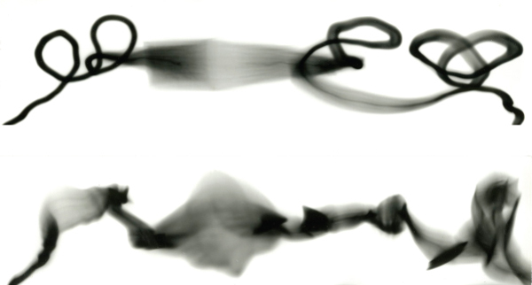
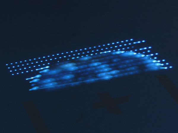
The goal of this project was to use light at the end of the 6-axis robot as a form of image making and projection. The concept behind this was the idea that digital imagery needs a way to be translated into the physical world. Pixels to Photons. By using programs and computer tools like Rhinoceros 4.0/5.0, Grasshopper, Processing, and Robot Studio, tool paths could be generated for the robot to translate the selected image onto photosensitive paper. The following images show the initial tests, tool design, and some final works.
Initial Studies
To test focusing light onto photosensitive paper I began by putting a lens underneath a dark room enlarger. These were successful but could not be replicated because the light is only visible at a point during exposure and the whole image is not revealed until placed in the developer solution. The robot would be able to make the same print several times without much variation.
Tool Design
The next step in the project was to design a focused light tool head for the robot. I began by simply taping a 12in cardboard tube to the end of the robot with the LED tool design for our first light writing project. At the end of the tube was a lens. Initially the light was to intense for the paper even when the robot was running at v800. I fixed this issue by laser cutting a light cover with a small 1/16 in hole in the center. This helped tremendously and the robot could run at a slower and more controlled speed. The final tool design used a 3D printed mount that attached the tube to the robot, held the LED and cover in place and kept the whole assembly stable.
First Tests
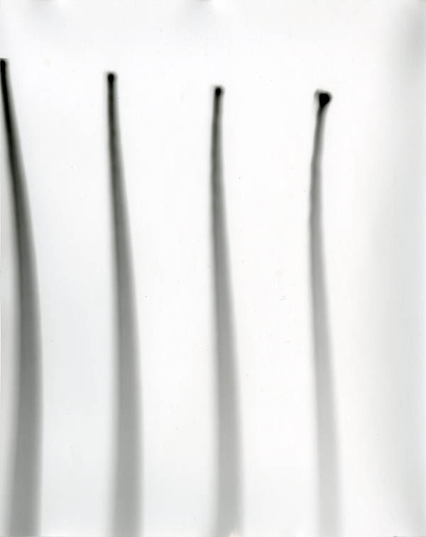
The first experiments were gradient strokes that moved across the paper starting in focus and then moving out of focus. This was where I discovered the need for a light cover to control the light intensity. These were created by placing pints in Robot Studio. The robot ran at v800 for these prints.
Light Writing V 2.0
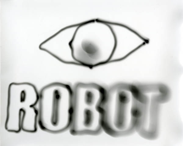
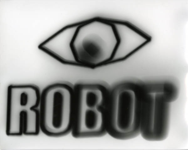
After the gradient I decided to reuse my light writing technique of moving geometry from Rhino to Robotstudio for the robot to trace. I choose to have the robot write, I Robot. I tested the writing at 2 speeds, v500 and v100. The v500 had a shaky quality to it because the tube was only taped to the robot. The v100 print was much darker but more controlled in the line quality.
First Image Test Grasshopper
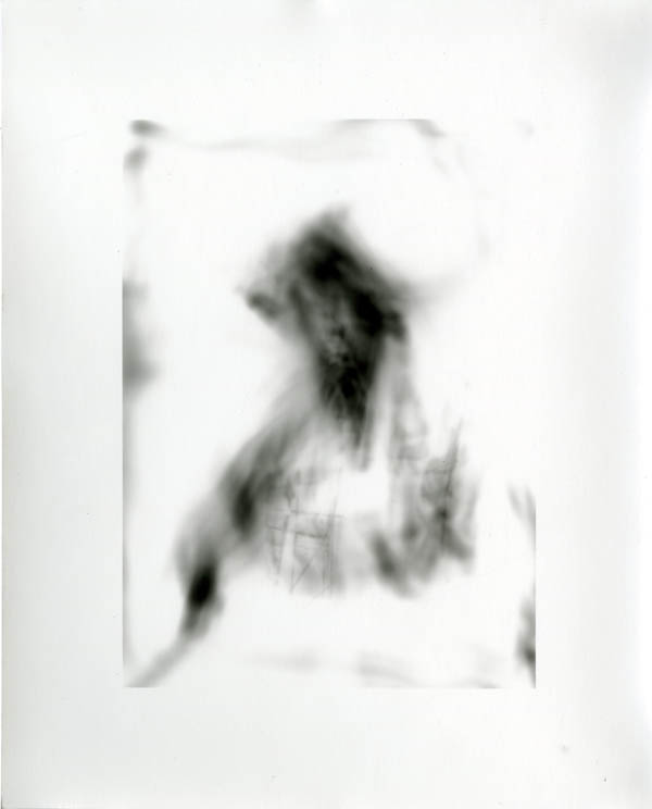
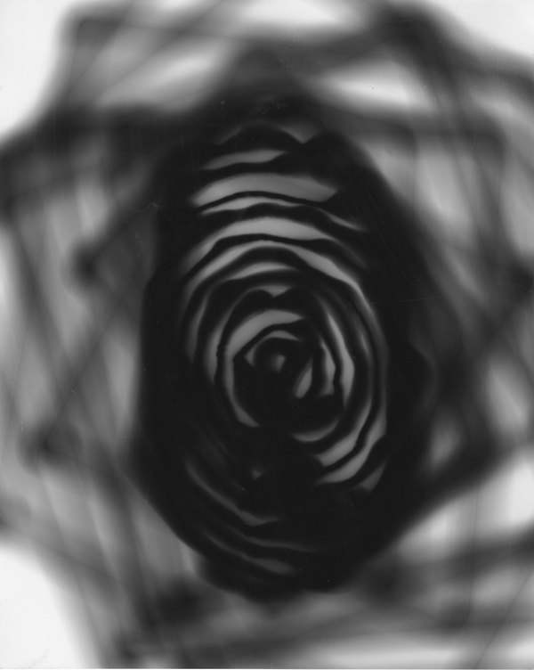
The next test used a base image of a man’s shadow projected on a curtain of trace paper (courtesy Caroline Record) and used a Grasshopper chain to create a continuous tool path for the robot to follow. I used Rhino to create a height field surface from the image then projected a linear path to the surface to plug into Grasshopper. Grasshopper generated a series of points for the robot to follow and created the code. I brought this code into Robotstudio and had to fix the orientation of the points. Once this was cleaned up the robot created the prints at 2 speeds, v100 and v500.
Thumb Print, Print
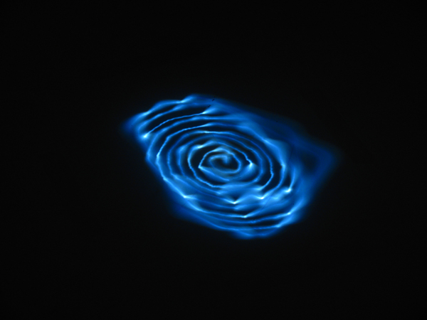
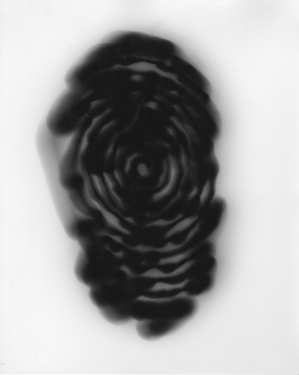
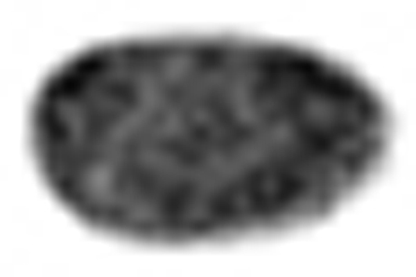
The second image I choose for the robot was a scan of my own thumb print. I wanted to give the Robot and identity, or at least let the robot create its own version of an identity. This was done the same way as the last set with Grasshopper and tool path curves. This time I created a spiral path that would work better with the thumb print style. The problem with the spiral was that it left a lot of excess path that was not changing height. In the second attempt I removed the excess curve. This was the first print with the 3D printed tool head.
Raster Finger Print
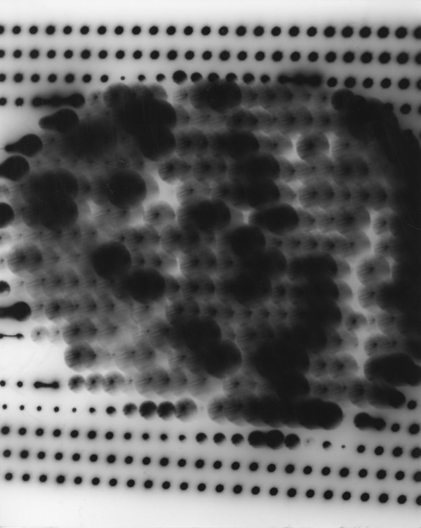
After the Grasshopper experiments I decided to switch to using Processing Code to generate the robot Rapid code. I viewed this switch as changing from vector based tool paths to raster point projection. In the Processing code each pixel of an image is translated into a height that the robot moves to and flashes the LED for a fraction of a second. I continued using the thumb print from before but I had to size the image down to 30×20 pixels. More than this and the program crashed and the time it took for the robot to go through the motions would be exponentially increased. It was much faster using Processing to get the code for the robot because it could be generated and transferred directly. But the downside was the time was increased when the robot had to pause at each point and flash the LED for .25 seconds.
Gradient Test
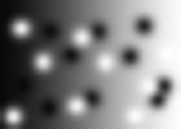
The last set I was able to do for the project was a gradient test in order to remove some variables and just focus on the light quality of the image. I set up a gradient from black to white with several areas of pure white and black splotches. This way I could adjust single factors as I explored the image making process.
Video
Here is a video link to the Robot in action.
http://www.youtube.com/watch?v=Xu-gBYX_ABI
Conclusion
With more time I could keep tweaking this design and expand the subjects and images that the robot could produce. Over all I view this as making significant progress towards a new and unique way to create print images.

